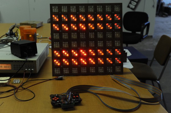
Over the past few days, I’ve been working on completing a project thats been on my mind for a while. The idea was to build a giant version of a MeggyJr RGB pixel game kit by Evil Mad Scientists, like what a big box store might use as a display unit in an alternate future where they sell cool electronics kits. The project has morphed a bit over time- originally, it was to be just a scaled up version of the handheld, complete with giant buttons and buzzer. I may still attempt that in the future, but for now the project consists of a large LED grid that works as a drop-in replacement for the regular-sized screen.
There’ still a reasonable amount of work to do on the project, but it’s getting closer, and this morning I was finally able to play the MeggyBrite program on a large grid :-). I still have to finish the enclosure and add a diffuser screen, however this seems like a good time to put up some documentation, so here goes:
There are three main components to the project: the RGB pixels, the laser cut enclosure, and the Meggy adapter board. Here’s an archive of all of the design material needed to make the board, and a short description of each component of the project.
RGB pixels
![]()
For whatever reason, I envisioned the display as being made up of a bunch of discrete pixel units, which would then be wired in a grid. Looking back, this is a pretty foolish way to build it (better would be to use larger breadboards, or pre-made modules like the ShiftBrite). Anyway, I had a whole bunch of 10mm LEDs, so I decided to design up a board to fix 3 each of the red, green and blue LEDs, forming a single RGB pixel. You need 64 of these for the whole array. I made them by hand using pre-sensitized PCBs, as explained in Collin Cunningham’s Circuit Board Etching tutorial. Thanks to Issac for helping me solder them together!
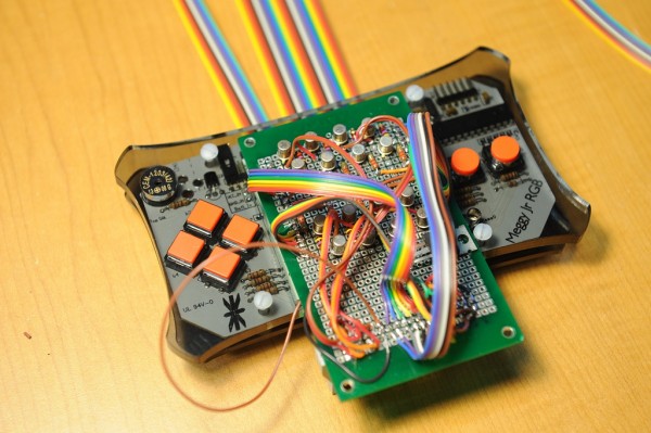
Adaptor Board

The adapter board is designed to plug into an unmodified MeggyJr, so that you can use it in portable mode with the regular screen, or go for the large screen edition at home. It has pass-through connections for each of the 24 column connectors, and a step-up driver on each of the 8 row drivers, allowing the Meggy drive hardware to control the higher voltage required to run the sign. Finally, it has an LM7805 chip to provide power to the Meggy. I didn’t draw up a schematic though, so you are on your own for this one :-).
Enclosure

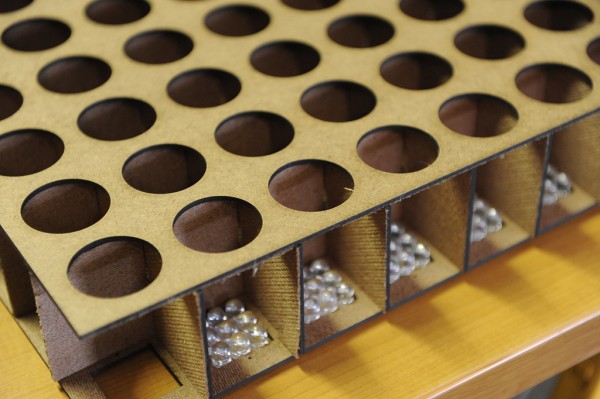
The enclosure is meant to look like a large version of the 8×8 RGB display. I drew up a design in Inkscape, and my friend Brandon Barber laser cut it for me in hardboard. The basic form is right, but I had to make a bunch of modifications, so I’d suggest using the design files as inspiration only.
I’m planning to have the display set up at our Hack Pittsburgh table at Maker Faire Detroit, so you should stop by and check it out!

