
Update: The Arduino system is fine; the only thing you have to take into consideration is the 9.54 hour rollover event, which Rob Faludi has provided an excellent solution for here. I made up a nice little over-analysis of the issue, available here.
I have been wanting to make a variable-speed clock for a while, so this weekend I picked up a cheapish clock unit (thrift stores are a great source!), and played around with using the Arduino to control it. In summary, I was able to get everything going, but there are some issues with the Arduino software that are going to prevent making it a really accurate clock. Explanation, source code after the break.

Part 1 – Hardware
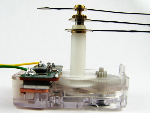
The mechanical bit is quite simple. The clock functions in a similar fashion to a stepper motor, in the sense that you charge an electric coil to get the mechanical bit to move forward a precise amount. In this case, each firing moves the second hand one second position forward (and makes the familiar tick noise). To ‘fire’ the electric coil, you simply put a voltage across it. The only complicated bit is that you actually have to reverse this voltage to advance the clock to the next step. This is accomplished by using two of the Arduino pins, and switching their polarity. (note: click on the picture to view the embedded notes). On the clock I dismantled, there was a little embedded controller. I used a razor blade to cut the copper lines between that and the connections to the electromagnet so that the original chip would be disconnected, and left it alone.
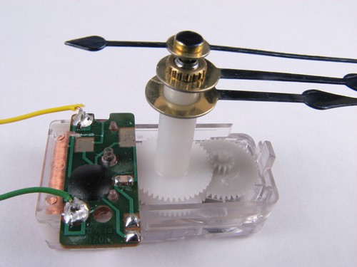
When we engage the coil by putting a voltage across it, it starts to draw current which then sets up a magnetic field through the coil. This magnetic field then applies a force to a permanent magnet that is attached to a gear, causing it to rotate and line up with the electromagnet. This gear turns exactly 180 degrees, and is connected to a series of gears that translate the 180 degree rotation into a 6 degree rotation (a 1:30 gear reduction). For the next cycle, we have to reverse the voltage that we apply so that the magnetic field we create will be in the opposite direction, and cause the permanent magnet to rotate again. One could also imagine a mechanism using a spring and a ratchet to pull the permanent magnet back into position, but that is not how these clocks work.
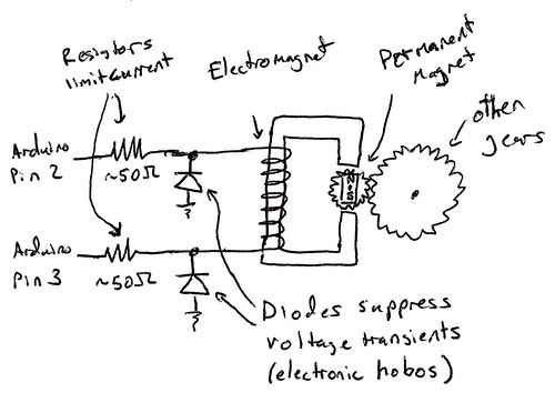
So, knowing all this, we should be able to connect up each end of the electromagnet to the Arduino and have it working. Because it is such a low power device (they are made to run on a single battery for months, if not years), it can be powered directly from the Arduino ports. There are only two things we have to consider in the circuit. First, a resistor should be placed in series with the coil to limit the amount of current it can draw. I chose two resistors with a value in the range of 50 ohms, and placed one at each end of the coil. You may need to experiment with these values to see what works. Second, discharging and charging the magnet can create high voltage spikes (it is basically an inductor), so it is recommended to place diodes from ground to each of the electromagnet. This will help prevent the voltage from going any lower than the diode drop, which is probably around .7 volts for the diodes I chose.
Part 2 – Software
Here is an example routine demonstrating how to get the clock to work. The doTick() function does all of the hard work, keeping track of which way the clock has to be pulsed next. This example driver is intended to simulate a standard clock. The speed that the clock ticks at can be adjusted by modifying the 1000 ms delay in the loop() function. This is actually where my project is going- I want to try out some fun things with innocent looking clocks that are completely bogus.
Unfortunately, there seem to be a few issues with the millis() command as I am using it, especially for clock control. The first problem is that it doesn’t look like it is actually ticking at a rate of 1ms. Based on the clock division that is being used (and assuming the system clock is 16 MHz), it appears that it is ticking slightly fast, with a period of .976ms. This is possibly not a big issue for most applications, but it is a showstopper for a clock- that is simply way too much error. It looks like there is also an issue with the millis() command producing strange output near the end of its range, but I am still looking into that one. Based on these points, I think I am going to pick up a real-time clock chip and use that as a timebase for my clock. I have seen them for around $4 so they should not be to big of a deal to integrate into a project.
// Clock Tick Demonstration // // By Matt Mets, completed in 2008 // // This code is released into the public domain. Attribution is appreciated. // // This is a demonstration on how to control a cheapo clock mechanism with an Arduino. // The clock mechanism works by using an electromagnet to pull a little fixed magnet, // similar to how a DC motor works. To control this with the Arduino, we need to hook a // wire up to each side of the electromagnet (disconnect the exisiting clock circuity if // possible). Then, hook each of the wires to pins on the Arduino. I chose pins 2 and 3 // for my circuit. It is also a good idea to put a resistor (I chose 500 ohms) in series // (between one of the wires and an Arduino pin), which will limit the amount of current // that is applied. Once the wires are hooked up, you take turns turning on one or the // other pin momentarily. Each time you do this, the clock 'ticks' and moves forward one // second. I have provided a doTick() routine to do this automatically, so it just needs // to be called each time you want the clock to tick. // ////// Board Setup ///////////////////////////////////////////////////////////////////////// extern unsigned long timer0_overflow_count; int clockA = 2; // Set these to the pin numbers you have attached the clock wires int clockB = 3; // to. Order is not important. int tickPin = clockA; // This keeps track of which clock pin should be fired next. // Initialize the IO ports void setup() { pinMode(clockA, OUTPUT); pinMode(clockB, OUTPUT); digitalWrite(clockA, LOW); digitalWrite(clockB, LOW); Serial.begin(9600); } // Move the second hand forward one position (one second on the clock face). void doTick() { // Energize the electromagnet in the correct direction. digitalWrite(tickPin, HIGH); delay(10); digitalWrite(tickPin, LOW); // Switch the direction so it will fire in the opposite way next time. if (tickPin == clockA) { tickPin = clockB; } else { tickPin = clockA; } } // Main loop void loop() { unsigned long startTime = millis(); unsigned long temp; // Pretend to be a regular clock, and tick once a second. while (true) { startTime += 1000; // Wait until a second has passed. Note that this will do ugly things when millis() // runs over, so we only have about 9 hours before this version will stop working. while (startTime - millis() > 0) {} doTick(); } } |
Hey Mahto!
Nice Write Up! Got it all working nicely, but I’m wondering after you made the clock go crazy how you could get it to advance to the original time before it went batty? I’m doing something that uses the Pomodori method – so 25 minutes it works, then goes on a ‘break’ and spins like crazy for 3 minutes then goes back to the normal ticking method. My challenge – how do you keep track of the actual time? or how do you remember the original position before it goes crazy then bring it to the position that it would be at 3 minutes later in actual time?
Thanks!
Oh, that would be sweet! There isn’t any feedback in a regular clock mechanism, they are open loop control. Your best bet is probably to count how many ticks the clock makes during the crazy time, then figure out how many it was supposed to make, and keep spinning the clock until the ticks it actually made divided by the total ticks in a 12-hour revolution is equal to the ticks it was supposed to make.
Hey Mahto! Got it working! I’m working on a write up now and will post it once it’s ready. Turned out to be a really fun project, thanks for laying the groundwork!
Hello again!
I already commented here 2.4 years ago that this article provided the foundation of my own clock project. News is, I finally translated the documentation of my project in English:
http://unsecure.logre.eu/wiki/24-hour_analog_clock
Summary: 24-hour one handed wall clock, Arduino replaced by a battery-powered bare ATmega, watch crystal driving the asynchronous timer/counter.
Regards, — Edgar.
Edgar, est-ce que vous pouvez s’il vous plaît ajouter la capacité d’ecrire des commentaires sur votre site web? Aussi, merci beaucoup por votre article.
And thanks to you too mahto!
~Gabriel Staples
http://electricrcaircraftguy.blogspot.com/