
Please note: The library described on this page was originally written for an extremely old version of the Arduino software. I’ve modified the project to work with Arduino 18, the new version is here: NikonRemote.zip. Download and unzip in your libraries directory to use.
An intervalometer is a device that sends out a signal at regular intervals. When hooked up to a camera, they can be used to take time lapse images, bracket exposure lengths and precisely time long exposure images (over 30 seconds) that the built-in timer on the camera cannot normally generate. When hooked up to a flash, they can be used to create a strobe effect. Being this useful, there are many different DIY projects to make them. Unfortunately, most of them work by triggering an electronic cable release, which my Nikon D40 and N75 happen to lack. Luckily, though, both of these cameras do sport a nice infrared control port. This brings us to this project- an infrared remote intervalometer. Todays portion of the project is to get the microcontroller to talk to the camera.
The most straightforward approach to this would be to take apart an existing remote and fire its button with a microcontroller. However, that didn’t sound like much of a challenge, so instead the goal became to train the micro to output the signals itself. A quick search fished out a well-documented solution by one San Bergmans. The routine is written in assembly to generate an accurate signal. I chose the Arduino as my platform, and figured out that it is pretty straightforward to include assembly inside of a C++ file. So, I ported San’s code to the Atmega168 that my Arduino is based on, and it appears to work quite swimmingly. The routine is wrapped up in a library, so using it is as simple as adding the library to your project and calling the Snap() function. There are a couple of caveats to this code,though: it (currently) only works on pin 12, and will only support the default clock frequency (16MHz?). Code after the break.
To use these, place them in a folder named NikonRemote, which should be located in the hardware/libraries/ section of your Arduino installation. Then, restart (or just start) the Arduino program, add the library to the project, and create the object in your sketch:
NikonRemote remote(12); |
Whenever you want to trigger the camera, just do this:
remote.Snap(); |
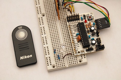
Oh, and don’t forget to attach an IR LED to pin 12, with some sort of current-limiting resistor. Tip: You can test if the IR LED is in the correct orientation by powering it up and looking at it with a digital that has a live preview.
NikonRemote.h:
#ifndef NikonRemote_h #define NikonRemote_h #include "WConstants.h" class NikonRemote { public: NikonRemote(unsigned int port); void Snap(); private: unsigned int _port; }; #endif |
NikonRemote.cpp:
// // NikonRemote // // This is an evil Arduino library that uses inline assembly to generate an IR // signal capable of triggering a Nikon SLR camera. // // By Matt Mets, October, 2008. // // Adapted from San Bergman's 'ML-L1 / ML-L3 IR remote control replacement' // http://www.sbprojects.com/projects/nikon/index.htm // // Note: At time of writing, it isn't clear what license it can be used under. // I will contact the author about this. // Note: This is an incomplete implementation. It requires the output LED to // be on pin 12. #include "NikonRemote.h" NikonRemote::NikonRemote(unsigned int port) { pinMode(port, OUTPUT); _port = port; } void NikonRemote::Snap() { // Definitions: // r16: port ON value // r17: port OFF value // r18: burst delay counter // r19: burst counter // r20: end delay counter // r21: port mask // 0x03: Port B input register // 0x05: Port B output register asm volatile ( "\n\t cli" // Disable interrupts "\n\t push r16" // Save context "\n\t push r17" "\n\t push r18" "\n\t push r19" "\n\t push r20" "\n\t push r21" "\n\t in r16, 0x03" // Calculate on and off port values "\n\t ori r16, 0x10" "\n\t in r17, 0x03" "\n\t rjmp COMMAND" // Jump to the command routine "\nNEXTPULSE:" "\n\t ldi r18, 68" // Count to 9 for one low pulse "\nSENDBURST:" // Low period delay loop "\n\t dec r18" "\n\t brne SENDBURST" "\n\t nop" "\n\t out 0x05, r21" // Set the output to mask "\n\t ldi r18, 68" // Count to 9 for one high pulse "\nBURSTLOOP:" "\n\t dec r18" "\n\t brne BURSTLOOP" "\n\t out 0x05, r17" // Set the output low "\n\t dec r19" // Determine if another burst should be performed. "\n\t brne NEXTPULSE" "\n\t ret" "\nCOMMAND:" // 2000us on "\n\t ldi r18, 65" // initial pulse = 65 "\n\t ldi r19, 76" // count = 76 "\n\t mov r21, r16" // Mask on "\n\t rcall SENDBURST" // 28ms off "\n\t ldi r18, 65" // initial pulse = 65 "\n\t ldi r19, 250" // count = 250 "\n\t mov r21, r17" // Mask off "\n\t rcall SENDBURST" "\n\t ldi r18, 65" // initial pulse = 65 "\n\t ldi r19, 250" // count = 250 "\n\t mov r21, r17" // Mask off "\n\t rcall SENDBURST" "\n\t ldi r18, 65" // initial pulse = 65 "\n\t ldi r19, 250" // count = 250 "\n\t mov r21, r17" // Mask off "\n\t rcall SENDBURST" "\n\t ldi r18, 65" // initial pulse = 65 "\n\t ldi r19, 250" // count = 250 "\n\t mov r21, r17" // Mask off "\n\t rcall SENDBURST" "\n\t ldi r18, 65" // initial pulse = 65 "\n\t ldi r19, 64" // count = 64 "\n\t mov r21, r17" // Mask off "\n\t rcall SENDBURST" // 400us on "\n\t ldi r18, 65" // initial pulse = 65 "\n\t ldi r19, 15" // count = 15 "\n\t mov r21, r16" // Mask on "\n\t rcall SENDBURST" // 1580us off "\n\t ldi r18, 65" // initial pulse = 65 "\n\t ldi r19, 60" // count = 60 "\n\t mov r21, r17" // Mask off "\n\t rcall SENDBURST" // 400us on "\n\t ldi r18, 65" // initial pulse = 65 "\n\t ldi r19, 15" // count = 15 "\n\t mov r21, r16" // Mask on "\n\t rcall SENDBURST" // 3580us off "\n\t ldi r18, 65" // initial pulse = 65 "\n\t ldi r19, 136" // count = 136 "\n\t mov r21, r17" // Mask off "\n\t rcall SENDBURST" // 400us on "\n\t ldi r18, 65" // initial pulse = 65 "\n\t ldi r19, 15" // count = 15 "\n\t mov r21, r16" // Mask on "\n\t rcall SENDBURST" "\n\t pop r21" // Restore Context "\n\t pop r20" "\n\t pop r19" "\n\t pop r18" "\n\t pop r17" "\n\t pop r16" "\n\t sei" // Enable interrupts "\n\t" ); } |
Thanks for the project and great documentation! I’m having some problems when using your code, though.
The code:
#include
void setup()
{
NikonRemote remote(12);
}
void loop()
{
remote.Snap();
}
Result:
In file included from D:\Program Files\Arduino\hardware\cores\arduino/WProgram.h:4,
d:/program files/arduino/hardware/tools/avr/lib/gcc/../../avr/include/stdlib.h:80: error: expected unqualified-id before ‘int’
d:/program files/arduino/hardware/tools/avr/lib/gcc/../../avr/include/stdlib.h:80: error: expected `)’ before ‘int’
d:/program files/arduino/hardware/tools/avr/lib/gcc/../../avr/include/stdlib.h:80: error: expected `)’ before ‘int’
d:/program files/arduino/hardware/tools/avr/lib/gcc/../../avr/include/stdlib.h:111: error: expected unqualified-id before ‘int’
d:/program files/arduino/hardware/tools/avr/lib/gcc/../../avr/include/stdlib.h:111: error: expected `)’ before ‘int’
d:/program files/arduino/hardware/tools/avr/lib/gcc/../../avr/include/stdlib.h:111: error: expected `)’ before ‘int’
d:/program files/arduino/hardware/tools/avr/lib/gcc/../../avr/include/stdlib.h:144: error: expected identifier before ‘(‘ token
d:/program files/arduino/hardware/tools/avr/lib/gcc/../../avr/include/stdlib.h:144: error: expected `)’ before ‘(‘ token
d:/program files/arduino/hardware/tools/avr/lib/gcc/../../avr/include/stdlib.h:144: error: expected ‘,’ or ‘…’ before ‘(‘ token
d:/program files/arduino/hardware/tools/avr/lib/gcc/../../avr/include/stdlib.h:144: error: expected initializer before ‘)’ token
d:/program files/arduino/hardware/tools/avr/lib/gcc/../../avr/include/stdlib.h:176: error: ‘__compar_fn_t’ has not been declared
In file included from D:\Program Files\Arduino\hardware\cores\arduino/WProgram.h:6,
In function ‘void loop()’:
Well, the #include thing doesn’t show up correctly, but why is this?
Hi etharooni,
That seems pretty close; the only part that I see wrong is that the NikonRemote remote(12); bit should be before the setup() function, not in it. The compile errors don’t make sense to me- mind making that change and telling me what you get? This code is only one night old, so there could be something stupid that I missed.
Matt
Oh, and what version of the Arduino software are you using? I designed this for 11, but the newest is 12.
Heh, cool, I just picked up a D40 and was wondering what it would take to do something along these lines. Thanks for saving me the trouble.
The reason for the above poster’s error is the move from 0011 to 0012 and the troublesome “int()” macro. Search the forum to confirm but I think the problem is the “WConstants.h” include line–you might be better to just extract the definitions you require.
–Phil.
Ah, thanks follower! I’ll upgrade tonight and take care of this.
Matt
Perhaps:
s/with a digital that has a live preview/with a digital camera that has a live preview/
i really racked my brain trying to get the timing working in an arduino sketch for this using the delayMicrosecond command and a function like this to make it oscillate. are these timings so precise that you really need to use assembly to get them right? any feedback would by much appreciated!
void oscillationWrite(int pin, int time) { // this function will cause the LED to flicker at approximately 38KHz
for(int i = 0; i <= time/26; i++) {
digitalWrite(pin, HIGH);
delayMicroseconds(13);
digitalWrite(pin, LOW);
delayMicroseconds(13);
}
}
full sketch: http://make.refractal.org/?p=3
Hi Marc,
It’s probably not entirely necessary to use assembly. I tried out your code with my D40, but I had trouble getting it to trigger my D40 reliably :-/. I saw some jitter in the signal when I look at it with my scope, which I believe is called by an interrupt being called during your timing loop (disabling interrupts in the function cleared it up).
It might be possible to program one of the timers to generate the 38KHz signal, and switch it on and off with C++ code. That way the signal would be spot on, without having to resort to assembly.
Matt
Hi etharooni,
Ok, I built version 12 of the software, and as Phil suggested, it does seem to be WConstants. Just removing that include line fixes the problem for me.
Matt
Thanks very much Matt! Reliability issues were precisely my problem. Your code is working great, however, so thanks again!
Really? Take off the #include line? Okay… That really doesn’t make much sense to me.
Result:
error: ‘NikonRemote’ does not name a type In function ‘void loop()’:
I’m downloading version 11 now. I’ve been using v12.
Awesome! Version 11 works perfectly! I had to use a transistor to use make the IR LED bright enough, but it’s really awesome.
Thanks very much for the library.
Triple comment post!
Oh! I get what you mean by taking away the #include. Gotcha, not in the main program.
Anyway, is there a way of keeping the camera (d40x) in it’s remote mode, without getting out of it after a couple seconds?
@etharooni: Excellent! Glad it started working for you :-). My D40 has a setting in the ‘custom settings menu’ that lets you choose the remote on time duration. The maximum I can set is 15 minutes, which is probably the upper limit for this camera (I think most of the Nikons are the same) :-(. Of course, if you need a longer time, you could always make a mechanical plunger to press the shutter release on the camera periodically to wake it up… but I would start to be worried about battery life at that point. Oh, and I’m working on the next part of the project using version 12, so hopefully that won’t be an issue for much longer.
@marc: You’re welcome, good to hear that it works for you.
Pingback: Infrared remote control for Nikon D50 | refractal make
Pingback: » Blog Archive » Arduino Intervalometer, part one: code
Hey Matt – I too have been struggling with how best to put a menu together. Right now I’m thinking of using a serial lcd and three buttons – select, value up and value down.
I’m also using two timers, so that if you want to do really long exposure “bulb” timelapses you could send two signals ten minutes apart(one to open the shutter and one to close it), and then send a third signal (to start the next shot) a few seconds later.
I have also thought up other stuff like adding on a headphone plug so that different types of triggers could be used. I haven’t gotten very far on that though! Thank you very much for posting this – I have tried and failed at this several times.
Hi Ross,
Yeah, that sounds about right. I made a partial menu system with three buttons, but it seemed really un-intuitive to me, and I didnt like that I needed another button to start the counter. But I need to get something going soon because I want to do some long exposure star trail shots :-D. Let me know if you come up with anything… I’ll post mine eventually if i don’t figure out something nicer.
Matt
Hello, my name is nacho, I do not know much English, so it pardons my poor English man. I also have a Nikon D40 and I am becoming crazy to make an gadget that does timelapses with the camera. I have been seeing your project and is very very interesting. I would like, if you can, to see the scheme in which you connect the infrared LED to the Arduino plate. And to see, if you can, describe plus the project with some example. On the other hand, what Arduino you have? How much it cost to you?
Thank for all!!!!
Hey nacho,
I have the infrared LED connected in the same manner as a normal LED:
(pin 12) —–|>|—-/\/\/\—— (ground)
where –|>|— is the LED and —/\/\/\— is a current limiting resistor, say 220 ohms.
I’m using a Bare Bones Board from Modern Devices (http://moderndevice.com/), which costs ~$15. Because it does not have a USB connection, I am also using an Arduino< ->USB cable which costs $20. A normal Arduino would work fine, though :-).
I’ll have more details about the intervalometer project shortly, when I finish it.
Matt
Matt – one more question.
What are you planning on using for power? I’d love to be wrong, but even in my dual battery setup I can only shoot for a few hours max. I currently have a grip / intervalometer that I got from dealextreme. It lets you run two stock batteries at a time, and I run them down all the time.
_ross
Hey Ross,
When I shot a test time lapse video of water and candles melting (http://www.cibomahto.com/2008/10/october-thing-a-day-day-10-time-lapse-video/), which took around two hours, a single (stock) battery on my D40 worked just fine. I was using an externally powered flash as well, though. I believe I was taking a picture every 30 seconds. How often are you snapping a picture?
I’m not planning on doing this often, at least with the dSLR, because I’m concerned about wearing my shutter out.
Matt
yeah- i hear you on the shutter failure issue. I’m kind of weirded out on that as well.
here’s a link with some stats. http://www.olegkikin.com/shutterlife/nikon_d40.htm
I shot for about two hours one night with shutter times varying between 3 and 30 seconds. It was shooting most of the time – i.e. if it was a 30 sec shutter it had 1 sec between shots so most of the time the shutter was open (and I suspect drawing power)
I’ve been thinking of doing shots of plants growing, so I’m obviously going to need a solution for that. I assume that if you are shooting for a significant portion of the night you might run into it as well..
Ah, yeah, long exposures would be huge power drains. I suppose I was cheating with the flash, but that’s only appropriate for some circumstances (it would work for the plants though?). The AC adapters from Nikon are a total ripoff, but perhaps there is a DIY solution there :)?
Hello, Matt.
Can yo upload a “zip” with the structure of the folders and the archives of each? I already have a Arduino and I am trying to prove it, but it gives me several errors, and I believe that it is because I have bad the scheme of the archives. Thank you very much!
I obtained it thanks to you!
THANKS, THANKS, THANKS, THANKS !!!!
This is perfect!
THANKS Matt!
Hi Nachoad, Awesome!!!
Matt
Hey Matt
I’ve been playing with your code and Marc’s but I can’t make it work :S
I have Arduino Diecimila and the 0012 Alpha version of the software.
I had to change some stuff to have it compiling and my main code is this:
#include
NikonRemote remote;
void setup()
{
pinMode(12, OUTPUT);
}
void loop()
{
remote.Snap();
}
NikonRemot.h:
#ifndef NikonRemote_h
#define NikonRemote_h
//#include “WConstants.h”
class NikonRemote {
public:
NikonRemote();
void Snap();
};
#endif
shortened NikonRemote.cpp:
#include “NikonRemote.h”
NikonRemote::NikonRemote()
{
}
void NikonRemote::Snap()
{
(I haven’t changed this function)
}
It just doesn’t work accuratly, I had this on for like 10 minutes and the camera shot only once…
With Marc’s code I have a better accuracy (I removed the 1 second delay so its doing the code continuously and changed 26 to 26.3 and it got a lot better, but still not good enough)
Do you have any idea why this isn’t working? thank you very much!
Oh, and on my include I have it correctly on my code my it seeams your website removes stuff that looks like an html tag…
#include _NikonRemote.h_
Hi Paulo,
I missed a critical part in the function that is posted here- I forgot that you need to call the function twice, with a specific delay:
remote.Snap();
delay(63);
remote.Snap();
Let me know if that helps. It’s been rock solid for me so far.
Matt
Hey Matt! Thank you, that works great now
One more thing, I had to comment out the line where you call WConstants.h in the NikonRemote.h but then I had to comment out this too:
pinMode(port, OUTPUT);
because without WConstants he didn’t knew the OUTPUT constant. I moved this line to the setup() function.
Thanks again for your great code!
Paulo
Awesome hack! I don’t have an Arduino yet, but I hope someone likes me enough at Christmas to get me one!
I’m sure there’s a simple answer, but I was just wondering why you didn’t use one of PWM pins to do the 38kHz pulsing. Sounds to this noob like what they were meant to do.
Hi hurley, good luck this christmas! You might be able to use a PWM output to do this, I didn’t really investigate it. It seems like a counter might actually be a better option then a PWM, if you could program it to give you an interrupt after a certain number of counts (some of the PIC processors have this sort of feature). Driving it directly seemed the easiest way to get it working, especially since there was existing code that didn’t require much modification.
Hey,
here’s my contribution to this remote camera control problem
I check the PWM idea, it don’t work,
the PWM frequency is too small compared to the 38400 hz needed.
And I wrote a different version of the code without ASM,
you can find a description & the code here:
ilpleut.be
thanks
Pingback: A Little Off
Pingback: Nikon D Series Lightning Trigger with Arduino « SolarGap Technology
@Aurelien
Thanks for the most excellent code. I used it for my Nikon Lightning remote.
Solargap Technology Blog
I’m using this on a Arduino Mega. In addition to the changes from software version 11 to 12, this code ends up operating on the pin labeled 10 rather than pin 12 for me.
Hi,
I got your code compiling (and therefore working of course) on the latest 0017 Arduino IDE.
You just need to substitute
#include “WConstants.h” with #include “WProgram.h”
to get rid of the compiler errors.
That does the trick… Thanks for this nice bit of code.
Hello Matt,
can you maybe send me via e-mail the zip with the .cpp and .h. I did exacly what you say, but still non working. I´m really new on the arduino lenguage. I add the library. but don’t know if I’m missing the void setup() and void loop() to start the programm…
Thank a lot!!
Hi Carlos, thanks for your interest. Unfortunately, I don’t think I still have those files, but Tom Igoe just used the library in a project, you should check out his write-up:
http://www.tigoe.net/pcomp/code/category/arduinowiring/800
Hi there,
Just seen your code – for those like me that don’t have the Nikon remote I built my own IR sequencer to do the same thing:
http://luckylarry.co.uk/2009/07/arduino-ir-remote-intervalometer-for-nikon-d80-that-means-timelapse-photography-yarrr/
So you just stick an IR LED in the pin 13 of Arduino and send the pulsed signal to send to the camera to take the photo.
Cheers,
Larry
@Larry
Cool, thanks for sharing!
hi dear
i’ve found you project simply amazing.
are you still following blog?? i hope…
i’m a student in informatic engineering in Italy, i’d like to implement your work in hardware, with VHDL language.
it’s a project for university, NON COMMERCIAL.
i’d like to talk a bit with you…
where did you found documentation or datasheet to know how “talk” to camera and timing?
does anyone where i could found those info/datasheet to know how dialogate with camera?
thanks a lot
giacomo
I don’t think the protocol is actually documented officially, however the implementation I used is documented here:
http://www.sbprojects.com/projects/nikon/index.htm
Good luck on your project, let me know if you get it working!
Cheers,
Matt
YitIRp
(pronounced Wyatt Earp)
By N6VMO
Our big off-road riding season kicks off at Thanksgiving. We gather with family and friends as well as several thousand other off-road enthusiasts in the western Mojave.
This has been a project on my list for some time. I have wanted to create a time-lapse movie of the entire weekend event. This requires the camera, a Nikon D40 DSLR, to snap photos every 6 minutes or so, over the course of 5+ days. It also means the camera needs to be hidden on a remote hilltop to encompass a large area.
I have envisioned using my laptop and DIYPhotoBits, http://www.diyphotobits.com, but this requires the laptop to be connected to the camera and enough power to run both for 5+ days. Not to mention leaving my expensive Nikon and laptop unattended in the middle of the desert.
Recently, I stumbled across an IR project that used an Arduino microcontroller to pulse an infrared LED to trigger a Nikon DSLR. This project simulates the Nikon ML-L3 Wireless remote control, but without human intervention.
http://blog.tinyenormous.com/2009/09/30/17-arduino-nikon-ir-intervalometer-code
Not being familiar with the Arduino, but knowledgeable using PIC microcontrollers, I decided to adapt it to a PIC16F648A, with an enhancement.
The Arduino project uses a potentiometer to set the time interval between shots. My PIC version uses 5 SPST (single pole/single throw) switches to set the time interval using a binary coded decimal scheme.
Switches 1 through 4 allow the photographer to select any number between 1 and 15, while switch 5 selects either seconds or minutes. The minimal interval is 1 second and the maximum interval is 15 minutes.
As an example, turning on switches 1 and 3 sets the interval to 5 seconds. The same switch settings and turning on switch 5, sets the interval to 5 minutes. This modification to the Arduino project simplifies and provides a faster, more accurate means of setting the interval.
The entire project can be downloaded from:
http://www.n6vmo.com/YitIRp/YitIRp.zip
The .zip file includes the PIC software files, schematic, PCB, and list of materials.
N6VMO