
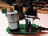
I thought this would be pretty fun; by reading the voltage from the center pin of the the servo’s potentiometer, it can be used as an input as well as an output device. Basically, you get a bunch of extra positional sensors ‘for free’. Some things that I could see this being useful for are:
1. Collision detection on unpowered arms (or even poor man’s torque detection by measuring the difference between what you requested and the actual position, assuming the servo doesn’t break).
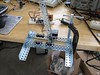
2. Physical keyframing; you move the arms of the thing you are animating manually, then press a button to record that position, repeat a number of times and then have the computer play it back (see video)
3. Haptic feedback, if you can control the servo fast enough (doubtful, but worth a try).
Source code after the break.
/****************************************************************************************************** * Using a servo for input and output * * by Matt Mets * Created 9 Feb. 2008 * * This demonstrates using the servo motor as an input device to record its own positions, which can * then be played back to animate whatever you are controlling. * * Servo control code thanks to: * Servo control from an analog input * http://itp.nyu.edu/physcomp/Labs/Servo * by Tom Igoe * additions by Carlyn Maw * Created 28 Jan. 2006 * Updated 7 Jun. 2006 * * The minimum (minPulse) and maxiumum (maxPuluse) values * will be different depending on your specific servo motor. * Ideally, it should be between 1 and 2 milliseconds, but in practice, * 0.5 - 2.5 milliseconds works well for me. * Try different values to see what numbers are best for you. * * This program uses the millis() function to keep track of when the servo was * last pulsed. millis() produces an overflow error (i.e. generates a number * that's too big to fit in a long variable) after about 5 days. if you're * making a program that has to run for more than 5 days, you may need to * account for this. ******************************************************************************************************/ /***** Variable Definitions ***************************************************************************/ int servoPin = 4; // Servo motor control line int analogPin = 1; // Line from servo potentimeter int recordButtonPin = 7; // Record button int playButtonPin = 10; // Playback button int statusPin = 13; // Status LED // Adjust these to fit your servo int minPulse = 500; // Minimum servo position (us) int maxPulse = 2200; // Maximum servo position (us) int refreshTime = 20; // the time needed in between pulses (ms) // Measure the minimum and maximum output voltages of the potentiometer and record them here. // Note: These should be measured over the full range of the servos motion. #define CALIBRATION_LOW_VOLTAGE 0.40 // Minimum potentiometer voltage (V) #define CALIBRATION_HIGH_VOLTAGE 2.00 // Maximum potentiometer voltage (V) // These are derived from the measured voltages above, are are computed during the setup routine int inputOffset = 0; // Input offset (ADC counts) float inputScale = 0; // Input scale (%) #define MAX_POSITIONS 50 // Maximum number of positions that can be stored int positionTable[MAX_POSITIONS]; // Table to hold each position int positionCount = 0; // Number of positions recorded /***** Functions ************************************************************************************/ void setup() { pinMode(analogPin, INPUT); pinMode(servoPin, INPUT); pinMode(recordButtonPin, INPUT); pinMode(playButtonPin, INPUT); pinMode(statusPin, OUTPUT); // Calculate the input offset and scale factors, based on hand-measured data // 204 = counts per volt inputOffset = CALIBRATION_LOW_VOLTAGE * 204; inputScale = 1024/((CALIBRATION_HIGH_VOLTAGE - CALIBRATION_LOW_VOLTAGE) * 204); // These are because I don't have a proper voltage rail on my proof of concept board, so I am using // pin 3 as a 5V source. You probably don't need these. pinMode(3, OUTPUT); // This pin powers some other pins so i dont have to wire... digitalWrite(3, HIGH); Serial.begin(9600); } // Sequence each recorded position void doPlayBack() { int position; long startTime; long lastPulse = 0; // the time in milliseconds of the last pulse // play back each step for a second for(position = 0; position < positionCount; position++) { startTime = millis(); while(millis() - startTime < 1000) { // pulse the servo again if rhe refresh time (20 ms) have passed: if (millis() - lastPulse >= refreshTime) { digitalWrite(servoPin, HIGH); // Turn the motor on delayMicroseconds(positionTable[position]); // Length of the pulse sets the motor position digitalWrite(servoPin, LOW); // Turn the motor off lastPulse = millis(); // save the time of the last pulse } } } } void loop() { int i; long analogValue; // the value returned from the analog sensor // When the record button is pressed, try to record the current sensor position if(digitalRead(recordButtonPin) == LOW) { if(positionCount < MAX_POSITIONS) { // There is room to store the positions, so do so. analogValue = analogRead(analogPin); // Read the analog input Serial.println(analogValue); analogValue = (analogValue - inputOffset) * inputScale; // Scale the compressed input to a full range analogValue = analogValue*(maxPulse - minPulse)/1024 + minPulse; // Precompute the pulse length positionTable[positionCount++] = analogValue; // Store in the table Serial.println(analogValue); // Debounce the input button digitalWrite(statusPin, HIGH); while(digitalRead(recordButtonPin) == LOW) delay(200); digitalWrite(statusPin, LOW); } else { // There is no more room to record positions, so flash the LED in protest. for(i = 0; i < 5; i++) { digitalWrite(statusPin, HIGH); delay(100); digitalWrite(statusPin, LOW); delay(100); } } } // User wants to play back the sequence if(digitalRead(playButtonPin) == LOW) { digitalWrite(statusPin, HIGH); doPlayBack(); digitalWrite(statusPin, LOW); } } |
It is a nice idea, good work man.
Pingback: Servo Hacking » project hal0
Very interesting idea. I’ll give it a try for sure. I’m curious how fast it can work for basic haptic feedback. Might not be perfect, but good enough for a lot of projects.
Pingback: anton - Vex Servo as an Input Device at antonolsen.com
Brilliant! Keep up the good work!
So simple, yet I haven’t heard of this idea before, well at least not with hobby servos.
Cheers!
Hi Matt, your thingaday thingy reminds me of something I required from people under my supervision (as Creative Director) which was to create something new every day. Not surprisingly, those who actually did this were the most creative and productive of all. I really like all your projects, there is a great stream of ideas and enthusiasm about them, sort of like digging for gold but without caring about whether you do find any. I came across your site because I am doing a robotic marionette (you can see my blog for that) and was searching for servo-feedback. So thanks for the idea. I am also using Vex for prototyping.
Arturo
And, hey, you have no address on your Amazon wish list, so I couldn’t send you a book!:-D
I have not gone over this in detail but think it is similar to the code for a rotery encoder ( optical ones can be salvaged from mice ) I have seen a suggestion that an op amp on the input ( prehaps with log response ) will allow this circuit to track down to very slow rotations. Nice job.
Thanks everyone!
@Arturo- Your project looks awesome. I fixed my Amazon list
@russ_hensel- I’m pretty sure this one is simpler than a rotary encoder, it’s just reading the voltage off of a potentiometer. You could certainly add some analog filtering circuitry (level shifter+amplifier) to make the output voltage span the maximum range of the ADC, which would probably give you better sensitivity.
Hi,
I am working on a project and I think this will work. Basically I want to control the knob on the back of a big analog clock and have it change the clock to a specific different time everytime a push a button. I don’t have an arudunio currently. Do you think this possible? Can you possibly help me with the code? I think I could modify your code to do this, right?
Thanks in advance,
Joe
Hi Joe,
What sort of knob is it that you have to turn? Servos usually can only turn back and fourth about 180 degrees, so they won’t be able to continuously turn a knob. If that won’t work for you application, I would suggest looking into a stepper motor- it might give you better control. There is an Arduino library for driving a stepper that looks like it might work. I’ve got a couple of projects that I want to use some steppers for, so hopefully I will have a better idea about them soon. I will do my best to answer any specific questions you have…
You actually reminded me of a clock-related project that I have been meaning to do. Now I have to go find a clock to hack
Hi Mahto,
Basically I am turning a little bolt with a piece of duct taped on it (for grip) that then turns the clock time adjustment on the back. I guess I need a stepper motor then.Thanks for the tips. Do you think ardunio is the way to go for this project? Thanks so much man!
Joe
Hi Joe,
Yeah, an Arduino is probably a good place to start for such a project. If you want to be a scavenger, you can also find some nice stepper motors in old (5.25″) floppy drives or scanners/printers. The stepper is a little complicated but probably the best for making the precise tuning that your project sounds like it will require. If anyone has better suggestions then a stepper I’d like to hear them…
Matt
Hi Matt,
Thanks for the tips. I will buy an Ardunio and get the stepper motor out of the collection of old computer stuff my dad has in the basement.
Thanks
Joe
Cool project. I could see this adapted to lots of toys!
excuse me.. i am interested in doing tis servo motor input/output. do u mind tell me wat i need(components)??
Thanks Alan!
Hi Zachary,
Do you already have a servo motor that you plan to use? It’s hard to give advice without knowing what you plan to work on. I used some pretty generic servo motors from a VEX robotics kit I have, and an Arduino clone to control the servo and read the potentiometer voltage back in.
Matt
This is really cool! Thanks.
Pingback: Top 40 Arduino Projects of the Web | Hack N Mod
Using servos for inputs could be handy for those robot dance competitions.
hi mate, I would like to make a sound module to my boat. but something using a mp3 player and a servo motor.
Thanks
Hi Paulo, I’m not sure what you are asking?
There is a new industry growing up around using DSLRs to shoot movies. A system like this could be used in a follow focus system. Somebody got bright and developed geared zip ties that can be wrapped around lens focus collars. The biggest headache has been getting the motors to stop at precise points. You program different focus points, and just push a button to change. Most systems currently sell fir around a grand. There are only three or four manufacturers fir the DSLR market, you might have a viable product.
That’s a really cool idea! I think my system might be a bit simplistic in terms of speed and accuracy, however it’s definitely possible to expand it to something more powerful!
I have been trying to repeat the same experiment but for some reason, its not working for me. Everything works well till it records the values of the potentiometer, but it refuses to play it back on pressing the play button. (I am using an arduino duemilanove board and a 9V battery to power it).
I like it. I only discovered arduino today and haven’t played with it yet. I’m looking at using it to drive 2 servos from pots and I have the program for that but I was wondering if I could combine this idea into as well. Would I be able to combine both on the one board?
Hi Mahto,
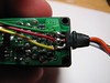
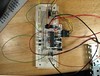
Excellent, do you have more in depth info on the breadboard setup?
I don’t have a schematic any more, but there is a little bit better detail on the flickr page:
https://secure.flickr.com/photos/cibomahto/2253942722/
is it possible to do this with a stepper motor?
Technically, you could use some pretty advanced techniques to do this with a stepper, but a servo motor is much more straightforward to use.
Hey Mahto,
You are simply the very best! I’ve actually been searching for a project like this on my journey towards becoming an electronic enthusiast like you .
.
Thanks so much for this post. I just placed an order for my own arduino microcontroller and would like this project to be my first.Can you pleeeeeaasssee send me the schematics or pictures of how you rigged the the microcontroller and the servo together…,please …:(
This seems pretty awesome. Right now I’m looking for something that would clone the signals that an r/c receiver sends to my quadcopter’s board. Basically I want to activate the servos without using an rx or tx.
I think this comes close. Do you happen to know of something more along these lines?
how can i modify this code to make my servo interact real time with my input servo. in other words when i adjust my input servo position i want the output servo to mimic it at the same time without any record and playback buttons.
To learn how to control a servo with Arduino, take a look at the sweep tutorial:
http://arduino.cc/en/Tutorial/Sweep
Now, modify the loop() function in that example, to save the value of the input servo to the output servo. It should look something like this:
// Read the analog input
analogValue = analogRead(analogPin);
// Scale the compressed input to a full range
analogValue = (analogValue – inputOffset) * inputScale;
//Finally, use the myservo.write() function to output to the servo:
myservo.write(analogValue);
Hope this helps!
Hi great tutorial and nice idea.
Just a quick question, about the serial programmer board, is this the primary way of communicating with the arduino i.e uploading the programme or is it for logging positions? i was thinking of trying this without the need for a pc attached and to upload the motion via a sd card is this possible? many thanks – si
Hello,
I am a small farmer /coder with cows and sheep for milking. I am learning arduino to design a cheesemaking machine. One part of the machine will have an agitator to make sure that the milk is heated evenly. I was envisioning using a servo motor with some sort of an attachment so that I could connect a standard stainless steel kitchen spoon.
Do you have any recommendations as to which servo motor I should use?
Thanks
Hi, great script!!!! Do you know if it’s possible to integrate another servo (like for using on a pan/tilt system) and instead of one button for reproduce the entire sequence, more button for store and repeat 1 position at once? (like button 1 x-y position1, button 2 x-y position 2 and so on…)!?!?!
In fact you can go much more further.
If you also take the motor driver control signals, you can measure quasi-static
error by the length of them, and extract approximately the torque
delivered by the servomotor.
Using position and torque you use arduino to implement an external
feedback controller for legged hexapod.
Great project. Thanks for posting this.
In keeping with the theme of real time recording of input, how long a single stretch of recoding would be possible with a typical Arduino platform?
Also, would into the possible to use a separate potentiometer as the controller, independent of the servo?
Thanks again,
Doug